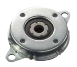
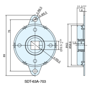
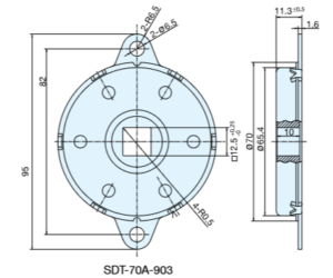
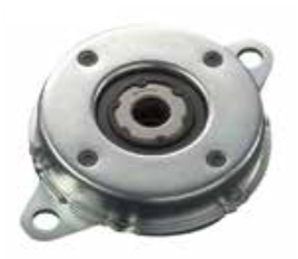
Disk Damper is a device that uses fluid resistance to provide damping. It’s designed for heavy-duty applications that require robust performance.
This damper is an infinite-angle type, where the body and end cap form a sealed oil chamber. As the shaft rotates, silicone oil flows gradually between the shaft and the body, creating a consistent damping force. It can be used individually or in pairs, with a shaft inserted between them to synchronize their operation
You can use one damper by itself or two together, with a shaft connecting them to make sure they work in sync. Disk dampers are essential in many applications, even though they’re often hidden from view. They play a key role in improving the quality, safety, and lifespan of various products. They come in two versions: uni-directional, which damps in one direction, and bi-directional, which damps in both directions.
2. Operating Principle and Specifications
Disk dampers employ the principle of fluid resistance to decelerate moving parts, using the viscosity of oil to generate the necessary “braking force.” This torque, which acts as the braking force, can be fine-tuned by altering the oil’s viscosity to meet specific damping requirements.
The damping action is achieved through the movement of fluid, which is forced from one chamber to another by a rotor. The speed of this damping process is influenced by both the fluid’s viscosity and the size of the fluid aperture through which it flows. Additionally, with the incorporation of a toothed plastic rack, designated as no. Q3150, disk dampers have the capability to provide damping along a linear plane. This feature offers an alternative to the conventional method of damping that occurs directly at the shaft, thereby expanding the range of applications where disk dampers can be effectively utilized.
3. Disk Damper Calculation
To accurately calculate the required torque for your specific application, you’ll need to take the following measurements into account:
t(torque)=w×0.5×ht(torque)=w×0.5×h
Where:
hh is the length from the pivot point to the end of the lid in centimeters.
ww is the weight of the lid in kilograms.
The torque force specified for each product, as detailed on the individual product pages, represents the maximum torque that the part can withstand before the damping force is overcome, leading to a loss of damping effect.
Important Note: After you have calculated the necessary torque, select a disk damper from our range that can handle the calculated torque for your application. It’s crucial to verify the compatibility by using the damper closing speed graphs. These graphs will help you ensure that the revolutions per minute (rpm) at the calculated torque value aligns with your desired lid closing speed.
If the desired rpm exceeds the capacity of the initially selected damper, opt for a damper with a higher torque rating and conduct a re-test. Conversely, if the rpm is too slow, choose a damper with a lower torque rating and re-test to achieve the optimal performance for your application. This process ensures that you select the most suitable damper to meet your specific requirements for smooth and controlled operation.
4. Torque Graphs for Temperature and Speed
To ensure the disk damper you choose is perfectly suited to your needs, adhere to the torque calculation formula and make use of the torque closing speed graphs. Here are some refined tips for the process:
Calculating Torque: Apply the formula provided to determine the necessary torque for your application, ensuring it aligns with the specific requirements of your project.
Consulting Torque Graphs: Refer to the torque closing speed graphs, which illustrate how varying temperatures and speeds affect torque. These graphs are essential for selecting a damper that performs optimally under the conditions your application will face.
Shaft Insertion Technique: When installing the shaft into the damper, ensure you rotate it in the direction opposite to that of the dampening action. This technique is crucial for preventing damage and ensuring the shaft engages correctly with the damper.
By meticulously following these guidelines and leveraging the provided resources, you can confidently select a disk damper that delivers the precise damping characteristics needed for your application, guaranteeing both efficiency and longevity of performance.
5. Disk Damper Applications
Disk dampers enhance various vehicle parts like arm rests, ashtrays, center consoles, glove boxes, handles, and storage compartments. They also improve the operation of personal gadgets including camcorders, cell phones, and small devices.
6. How to Use Rotary Damper
Torque Direction: Dampers can produce torque in either clockwise or counter-clockwise directions.
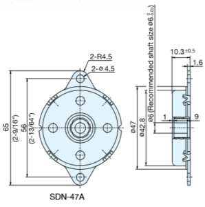
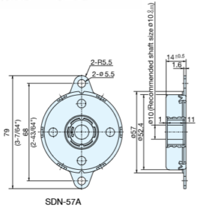
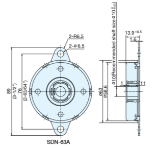
Shaft and Bearing: Ensure the shaft connected to the damper is supported by a bearing, as the damper does not include one.
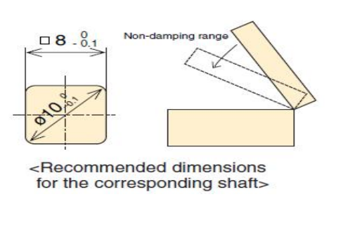
Shaft Dimensions for PTRD-47A: Follow the provided specifications for shaft dimensions to prevent slippage when creating a shaft for the PTRD-47A model.
Inserting the Shaft: When installing the shaft into the PTRD-47A, rotate it in the idling direction of the one-way clutch during insertion. Avoid forcing it in the opposite direction to prevent clutch damage.
Correct Shaft Insertion: For PTRD-47A, use a shaft with the specified rotation dimensions to ensure proper fit and function. An improperly fitted shaft can hinder the lid’s ability to close smoothly. Refer to the adjacent diagrams for correct shaft dimensions.
7. Performance Characteristics of Disk Dampers
Speed Characteristics: The torque of a disk damper is directly influenced by its rotation speed. Typically, the torque increases with higher angular speeds and decreases with lower rotation speeds. For instance, at 20rpm, the torque is lower, especially when a lid is initially closing, which results in a torque that is less than the rated torque.
Temperature Characteristics: The torque of the damper, known as the rated torque, is affected by the surrounding temperature. An increase in temperature leads to a decrease in torque, while a decrease in temperature results in an increase in torque. This variation is due to the changing viscosity of the silicone oil within the damper as the temperature fluctuates. The relationship between temperature and torque is depicted in the accompanying graph.
(Note: The repetition in points 3 and 4 seems to be an error in the original text. The information provided is the same as points 1 and 2, so it has not been repeated in the rewritten section.)
Email Us
Call us
If you have questions or comments about our stores, products or services, we’d like to hear from you.